Sprinkler Solenoid 24VAC Woes
See my Home Sprinkler notes
I have had many problems with my sprinkler system; decrepit failing 30 year old underground wiring, failing solenoid valves and their solenoids. Some of the old solenoid valves were replaced as they had mechanically failed. The multiple issues made it vary difficult to diagnose what was happening at any time.
I ended up replacing the wiring twice. The second time I used more robust sheathed multi core wiring and node control boxes with LED lights that confirmed power to each solenoid circuit at the node. This helps easily determine if the fault upstream or downstream the node point.
Basically at this stage the outstanding problem was the just failing valve solenoids. Interesting only the new valve solenoids were failing. The 30 year old valve solenoids and the pump contactor continued working without problems. I tried 3 different new solenoid valve types and all the solenoids failed, within a week to 6 months.
I have been using the Open Sprinkler V2.0 since about 2014, this is a 24VAC controller. I reached out to the solenoid valve supplier and asked them if they had any similar such problems. They indicated that some of the open source controllers were DC or perhaps allowing DC offset on to the valve solenoids. This did not make sense in my case the controller was designed as a 24VAC system and its circuit diagram clearly shows the output was a solid state AC relay output. The power supply was a 24VAC transformer rated to 1 Amp. Also why were only the new valve solenoids failing and not the old valves and pump contactor? That being said the valve supplier kindly sent me 4 replacement solenoids.
I reached out to Open Sprinkler about the matter, however they did not seem to understand and indicated that the controller was a 24 VAC type and DC was not an issue.
To fully resolve this issue I purchase a single channel digital oscilloscope and tested the voltage at the controller out and the node boxes closer to the solenoid valves. The operating measured voltage was between 25.8 and 25.2 VAC RMS. The wave form was very sinusoidal and the offset was negligible, about 0.2 V. On this basis the whole DC issue was closed out as not applicable in my case. The 24VAC supply voltage with no outputs operating, just the controller powered was 27.2VAC.
I would consider normal supply voltage tolerance to be minimum +/-10% this aligns with the IEC standard for electrical power distribution. So a 24VAC system should be able to absolutely reliably operate between 21.6 to 26.4 VAC. As the solenoid operation voltage was typically between 25 - 26VAC this condition is meet. The stand-by voltage was not a concern for the solenoid operation (as they are not powered) and the controller clearly had no problems with this having operated reliably for 10 years. Checking the controller circuit I would expect it would reliably operate with 24VAC ± 20% or 19.2 to 28.8 VAC. The controller solid state outputs had 40V snubbers which could start snubbing the sinusoidal peak voltage over 28.2 VAC RMS.
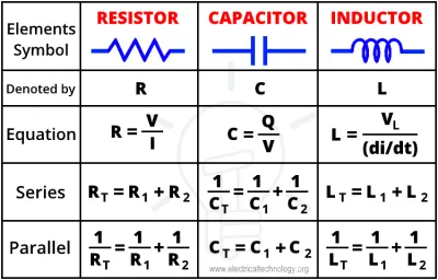
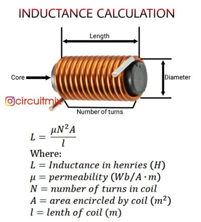
Next I measured the DC resistance of a new solenoid at 33.1 Ω. Based upon the specification printed on the Solenoid 24 VAC, 50/60 Hz, Holding 0.25 Amp and inrush 0.43 Amp maximum I calculated the solenoid impedance to be 96.0 Ω. This means the solenoid holding reactance calculates as 90.1 Ω. The solenoid apparent power is 6.0 VA and real power 2.07 W. With 25.2 VAC supply at the solenoid this becomes 0.264 A current, 6.68VA apparent power and 2.3 W real power. Reactance has the following relationship with Inductance and frequency, XL = 2π F L, where XL is impedance (Ω), F is frequency in Hz, L is inductance in Henry. So the with 60Hz the solenoid effective impedance increase from 90.1 Ω at 50 Hz to 108.2 Ω. At 24VAC 60Hz the solenoid current then drops to 0.21 Amp (was 0.25 Amp at 50Hz) with apparent and real power dropping to 4.87 VA and 1.49W. On my system with 25.2 VAC at the solenoid calculations show that adding a 12 Ω resistor into the solenoid circuit reduces the solenoid voltage to 23.9 VAC and current to 0.249 Amp. The voltage drop across the resistor is 3.2V and power drop 0.79 W. The resistor was rated for up to 1 W operation. A USA based brochure for the K-Rain Valve KR7101 gives the following specification for the valve: Voltage: 24VAC 60 cycles, 0.4 amps in rush, 0.2 amps holding. Pressure 20 psi minimum to 150 psi. This aligns well with the calculation showing 0.21 Amp at 24 VAC 60 Hz.
I measures the voltage across the resistor with the Oscilloscope at between 2.81 to 2.88 VAC RMS and resistor was measured with a multimeter as 12.1 Ω, so circuit current is 0.232 to 0.238Amp. This places the solenoid operation below name plate specification.
I measure the voltage across the resistor when operating an old solenoid valve and it was 3.03 VAC RMS, with calculated current of 0.25 Amp. Interestingly the waveform across the resistor on the new solenoids looked distorted, more triangular, whereas the old solenoid valves waveform was much more sinusoidal. I wonder if the new solenoid coils were saturating leading to the distorted current wave form, I don't know for sure, nor what the impact on the solenoid actual power draw would be.
As of writing I have only been running the system with the 12 Ω resistor for about 3 months. I had to replace 4 solenoids in the previous 3 month period. So it would seem the addition of the 12 Ω resistor has resolved the new solenoid failure problem. My calculations show I should be able to double the resistance up to 24 Ω if necessary and still have reliable solenoid operation, 2x 12 Ω resistors in series due to 1W power rating limit of each resistor.
About 9 months earlier the control wire to the pump contactor failed and I needed to get it replaced. The old wiring used speaker wire and it was replaced with sheathed multi core cabling rated for 24VAC sprinkler applications.
In summary:
- Old decrepit failing underground solenoid wiring replace with new sheathed quality multi-core wire with node boxes fitted and operation well for 5 months. The LEDs in the control nodes make system diagnostics much easier.
- New solenoid valves are dual rated for 50/60Hz and significantly relies upon the solenoid reactance. The reactance is directly proportional to the frequency that affects the operating solenoid current and power draw. In 50Hz applications the current and power draw are higher than 60Hz and hence the solenoid has less tolerance to over rated voltage. The use of a series resistor seems to solve this problem.
- I suspect the new solenoid valves are actually optimised for 60Hz operation not 50Hz and this has been the root cause of the new valve solenoid problems I have been having.
- A readily available 12 Ω, 1 W resistor at cost of less than $1.00 is a simple solution to rectify the solenoid failure problem.
Some additional comments:
- Multi faceted problem solving is significantly more difficult than single point failure analysis.
- Avoid the use of single sprinkler wiring in more complex larger sprinkler reticulation systems. The use of quality multi core cabling provided a much more reliable system.
- I do not like jar top style irrigation solenoid control valves, just a personal preference though.
- An inductor instead of a resistor may be a more effective solution to reduce the solenoid current and overall real power consumption, however resistors are cheaper and easier to get and also smaller. The 12 Ω resistor power loss is < 1W, where as an inductor would probably reduce this by a factor in the order of 2 - 5. Suitable 10 mH inductors are available for purchase, e.g. Mouser muRata Power Solutions 1410604C , which is rated at 10 mH, 4.34 Ω & 0.4 Amps, ±10%. However they are more expensive and larger than simple resistors. They also need to be ordered in instead of being readily available from the local electronics store.
Summary
After 12 weeks of reliable operation with no further solenoid failure the use of a 12 Ω resistor to limit solenoid current and power draw has rectified the solenoid failure problem. It appears the use of valve solenoids specified for dual 50/60 Hz use on 24 VAC are prone to failure with use on 50Hz supplies with voltage at solenoids greater than 24.0 VAC.

